For just $2, convert any existing wired doorbell into a smart doorbell; using ESPHome and Home Assistant

F

This article is going to show you how to convert your (existing) wired doorbell (also works for battery-powered chimes) into a smart, WiFi-enabled, doorbell. The essential components needed sets you back about $2, yes, that is correct, just two bucks. No soldering is required and you don’t have to be an electronics expert.

Photo of the resulting DIY Smart Doorbell on my test bench
The result of this DIY Smart Doorbell project on my test bench, ready to be installed

Integrating your doorbell into your smart home is a very logical step to take. Making your doorbell smart, allows you to do cool things with it, for example:

  • Turn the chime/bell off after a specific time, when the kids or you went to bed. Also, turn it on again in the morning.
  • Send out push notifications to your phone/tv/watch/smart speaker, on the doorbell button push.
  • Take a snapshot from a front door camera, on the doorbell button push.
  • Stream your front door camera to your TV, on the doorbell button push.
  • Ring the doorbell continuously in case of an emergency (e.g., smoke detectors triggered).

I have provided some of these automations for Home Assistant, as an example, at the end of this article.

The method I provide is, of course, not the only solution. However, I guarantee it is the cheapest out there and a great way to get into DIY. The feeling of having it made yourself is satisfactory beyond any other solution.

Are you curious yet?

How does a doorbell work; Before and after.

Before we start doing anything, let’s take a quick look at how a wired doorbell works. For this article, I am going to assume a wired and AC powered doorbell. However, battery-powered chimes are not that different, and I’ll provide instructions for that as well.

Shows a regular doorbell circuit/wiring schema
Regular doorbell circuit schema

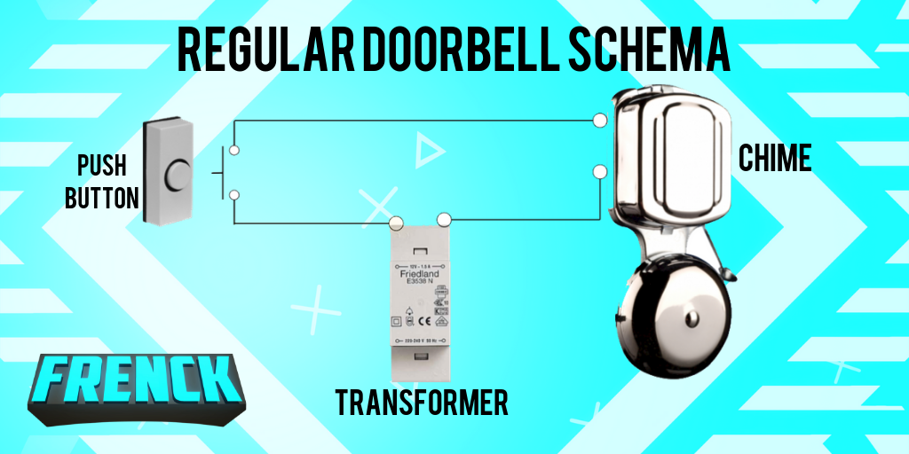
A pretty standard doorbell set up has a power supply, hooked up directly to the chime. Prevent the doorbell chime going continuously, the circuit is interrupted by the doorbell button, which acts as a switch. The circuit is only active/complete when the doorbell button is pushed. Hence, your chime turns on when someone pushes the doorbell button.

Shows an circuit/wiring schema for the DIY Smart doorbell
DIY Smart doorbell circuit schema

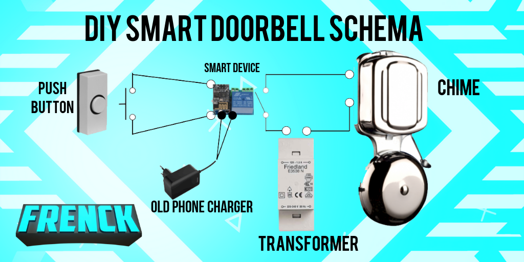
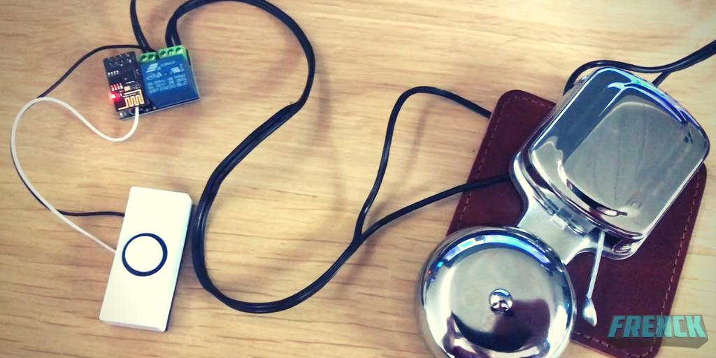
The image above should give you an idea of the result of this article. Basically, you are going to split your doorbell circuit into two separate circuits. One circuit detects the doorbell button push; the other circuit controls the chime. This split allows for controlling those separately, e.g., detecting a doorbell push from Home Assistant, without activating the chime.

The device we are using is going to act as a sensor for the doorbell button push, and acts as a switch for the chime. Effectively, we are moving the activation of the chime from the doorbell button, to the new device. Our new device needs power, and since the one used consumes 5 volts. Any old USB phone charger you have, does the job just fine.

Smart doorbell stuff you’ll need

To achieve this, you need some “stuff”. The $2 price tag is based on the actual device we are going to create, however, if you don’t have some of the needed tools, that would raise the total price. Nevertheless, the additional stuff is really cheap and are things that, in my humble opinion, every DIY home automator should have in their toolbox (for future projects).

Based on the country you are in, additional shipping costs may apply. I live in the Netherlands, and I’ve paid 1,80EUR in total, including shipping. Checking out the different sites for the right price helps. I’ve noticed the prices for these little boards vary, but getting it for around $2 is doable.

The main components

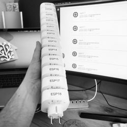
This project consists of just 2 parts. An ESP8266-based chip called the ESP-01S and a small board with a relay on it.

Product image of the ESP-01S chip

ESP-01S

The ESP-01S is one of the smallest WiFi boards available, that works ESPHome and Home Assistant.

Product image of the ESP-01(s) relay module board

Relay module

This relay module board for the ESP-01(S), It comes pre-soldered, and the ESP will just slide on top of it.

The nice thing about these two is that they fit together, are pre-soldered and often sold together. There is also another version of the ESP chip, without the S, the ESP-01. That chip is viable for use as well, however, the ESP-01S is an improved version and has double the amount of memory. Since the price difference is just a couple of cents, I would highly recommend getting the S version.

The board needs to be powered and requires 5 Volts. Lucky, most phone chargers provide those and I’m sure most of you have an old one around you could use.

That brings me to the shopping list of the main components needed:

Other tools and hardware

Besides the main components, you’ll need some other things for building it as well. Without a doubt, you need some screwdrivers and a wire stripper. A pair of tweezers can also help put wires to place, and for modifying to the board later on.

The ESP01-S chip needs to be programmed. To do that, you’ll need an FTDI adapter. If you have ever flashed ESP chips before (e.g., SonOff switches), you probably already have one. If not, you should get one! It is an essential tool to have when you are into home automation.

Product image of an FTDI adapter

FTDI Adapter

An FT232RL FTDI USB To serial converter adapter is a must a have
for any smart home enthusiastic to have in its toolbox.

Click here to get one

Additionally, some wire is needed. I always have a bunch of Dupont cables in stock. They are really helpful in many many projects I’ve done. It allows you to wire up prototypes really quickly as well.

Product image showing a bunch of Dupont wires

Dupont wires

Having a collection of Dupont wires with different male/female connector combinations, is useful to have around. It allows for quick DIY prototypes, but useful in final projects as well.

Product image of a Dupont crimper set

Dupont crimper

Alternatively, create your own Dupont wires using a wire crimper. It is way more flexible compared to pre-made wires.

Depending on where you are going to place the smart doorbell, you might be need a case as well. The resulting board is pretty small. Maybe it can already fit one of your electrical boxes. Another option is getting a small project box online, like this one:

Product image showing a small project box

Small project box

Small project boxes really finish a DIY project and make them look slick while protecting the electronics as well. For this project, a small box like this does the trick.

Needed software

Obviously, you need some software to pull this off. All software used is open source and free for you to use.

Home Assistant is my home automation hub of choice, and for this guide, I assume you are using it as well. However, this project can be used on other hubs as well (like Domoticz or OpenHAB). I’ve added a section at the end of the article for more information about this.

Modifying to the ESP-01S chip

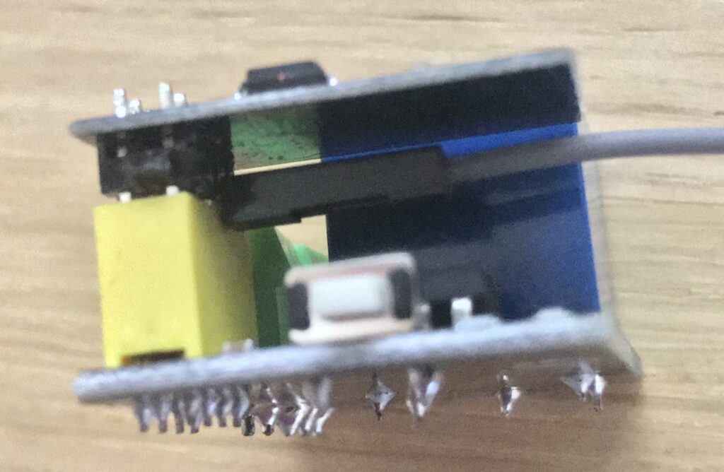
To make this setup work, you would have to make a small modification to the ESP-01S chip. Reason for this modification is that you have to free up an additional pin for connecting your doorbell button. These input/output pins, are called GPIO pins.

The ESP-01S has two GPIO pins available. Using the relay board, one of the GPIO pins is wired to the relay, the other is wired to a reset mechanism. Without this modification, a doorbell button push would result in a reset/restart of the chip, which of course, isn’t what we want.

Don’t worry, this modification is easy. We need to bend the GPIO2 pin from the ESP-01S. This allows you to access the pin for connecting the doorbell button, while disconnecting it from the relay board.

The lost reset functionality is later be restored via a software switch in ESPHome. Furthermore, the reset button on the side of the relay board isn’t affected by this and keeps working as a reset button as well.

Flashing the firmware on the chip

This project uses ESPHome to create firmware for the ESP-01S chip. I’m not going to make a full tutorial on how to set up ESPHome since that is really well covered on their website. So, before continuing, make sure you’ve set up ESPHome.

For the rest of this guide, I’m going to assume you are running Hass.io. However, the ESPHome getting started guide for non-Hass.io users is extremely detailed, and you should be able to adapt easily.

Creating, building and downloading the firmware

Create a file called doorbell.yaml; for Hass.io users, create the file in the /config/esphome folder, so you end up with the file: /config/esphome/doorbell.yaml.

Next, add the following contents to the file:

The above file shows a ESPHome project definition; the ESPHome project code, or also referred to as ESPHome YAML. The code describes the firmware allowing ESPHome to generate it. I’ve have tried to add as much additional text as possible to the above, to help you understand how it works.

On line 9 & 10, make sure to set your WiFi details or else you might end up with failures. Save the file and open up the ESPHome web interface; The doorbell project should appear!

Now, you should be able to validate, build and download the firmware from ESPHome. Let me show you a screen recording on how that works:

Animation on how to validate, compile and download ESPHome firmware
Doorbell ESPHome: Validate, compile and download

Uploading the firmware to the ESP-01S chip

Image shows my ESP-01S being flashes for the smart doorbell
Flashing my ESP-01S for the smart doorbell

Now you have the firmware (the downloaded doorbell.bin), you can start putting it onto the ESP-01S chip for use. This flashing procedure is the hardest part, and if you are new to this, please have some patience, it might need a couple of tries for you get it right.

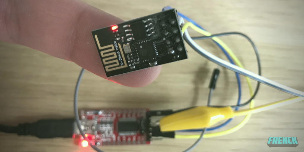
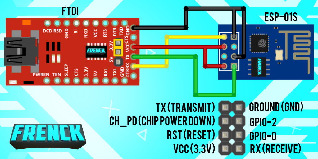
Start with wiring up the ESP-01S chip to the FTDI adapter, using some Dupont wires. Don’t freak out now, we only need to do this once. Once you’ve flashed the chip, future flashing/upgrades can be done Over-the-Air (OTA) via WiFi. Wire the FTDI & ESP-01S according to the following wire schematic:

Illustrates how to wire an FTDI adapter to an ESP-01S chip.
FTDI to ESP-01S Wiring Schema

Make sure to double-check the wiring and set the FTDI to 3.3V. Even if you are an experienced flasher of ESP chips, please note, the VCC/3.3V and ground wires being double wired! Although, I’ve used a very common FTDI board in this schema, your FTDI might look different, ensure you wiring up correctly by verifying the names on your board.

Ready to flash? Good!

Plugin the FTDI adapter to your PC, and start-up the ESPHome Flasher tool. Yes, I know, it is possible to flash directly from ESPHome itself, however, if you are like me: I don’t have the machine running Home Assistant near my desk. Furthermore, it can be quite a challenge for people running Hass.io on a virtual machine. The ESPHome Flasher is easy to use and just works from your desktop.

Select the available serial port, and load the downloaded doorbell.bin file, by clicking the “Browse” button. Start the flash procedure by clicking the “Flash ESP” button. The console shows you the progress and tells you when it finishes.

Animation on how to flash firmware using the ESPHome Flasher
Flashing firmware using the ESPHome Flasher

If this process fails, please make sure to check your wiring. A common mistake is mixing up the TX/RX wires between the FTDI & the ESP-01S. They should be cross-connected (TX -> RX, RX -> TX).

Installing and wiring your smart doorbell

Time to install your newly created smart doorbell. The following schema helps you to connect the wires correctly.

This image shows how to wire up your smart DIY doorbell.
DIY Doorbell Wiring Guide

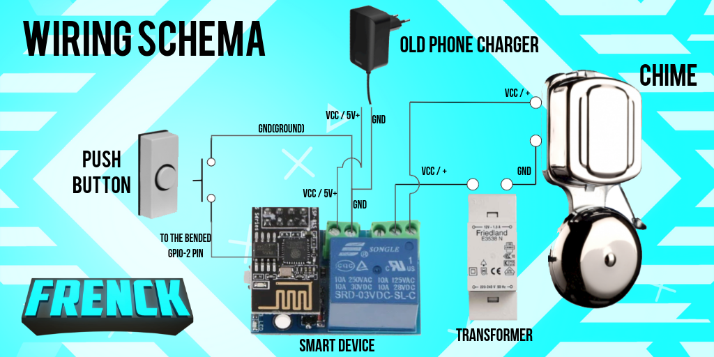
Please note, how the ground wire from the phone charger is shared with the push button. To hook up the push button to the bent GPIO-2 pin, I recommend using a Dupont wire, since you can slide it right onto the pin in that pretty tight space.

Photo of GPIO-2 wired with a Dupont wire
Wiring the GPIO-2 pin with a Dupont wire

If your chime is a battery-powered one, the schema does not differ that much. Just act like the transformer is not in the above image. The two connections from the battery-powered chime, connect directly connect to the board (to the COM and NO labeled ports).

Done? Awesome! Pushing the doorbell button should now ring the chime already! So basically, you’ve now ended up with what you had already…

Now you can continue to configure your smart doorbell in Home Assistant, let the fun begin!

Integrating with Home Assistant

Welcome to the easier part of this guide. Integrating your new, self-created, smart doorbell with Home Assistant. Home Assistant will discovery it automatically. The only thing you need to do is to activate it and unlock a bunch of new entities for you to play with.

This screen recording shows how that works:

Animation on how to integrate the DIY smart doorbell with Home Assistant
Integrating the ESPHome DIY smart doorbell with Home Assistant

Home Assistant smart doorbell automations

At this point, you have a WiFi-enabled doorbell. Is it smart already? Not really…

Adding some automations to Home Assistant would make it really smart! There are many automations one could create with this. However, let me give you a couple of basic and useful examples.

Sending notifications to your phone

This little automation sends a notification to our phone when someone is at the door. We have Apple iPhones and watches, so those notifications would end up on our wrist as well, even if the chime is disabled!

Disable the chime during the late hours

I have two kids. Nothing is more annoying than the sound of the doorbell chime about 15 minutes after you’ve put them into bed 😞. This little automation will disable the chime during the late hours and enable it again in the morning.

Streaming the front door camera when someone is at the door

This little automation is useful if you have a camera pointing at your front door. If you push the doorbell button, it will send out the camera stream of your front door camera to your living room TV 📺.

More smart doorbell automation ideas

  • Disable the chime when you arm the alarm when home, indicating you went to bed.
  • Use pressure sensors in your bed to turn off the chime when sleeping.
  • Create a camera snapshot when someone is at the door, and send it out to your phone.
  • Use the chime as an alarm bell as well, e.g., in case smoke or water leak is detected.
  • Use facial recognition on your front door camera, to disable the doorbell for the ones you don’t want to open the door for. E.g., an unknown person or your mother in law 😈
  • Prevent over abuse of doorbell pushes, by disabling it for a couple of minutes after it was pushed.
  • Hook the doorbell chime active switch into your voice assistant, allowing you to say “Hey Google, turn off the doorbell”

Optional changes and modifications

There are probably a hundred variations on this approach I took, but that was not the point of this guide. However, some are worth mentioning.

Using the chimes’ power supply using a step-down

In my case, my doorbell chime is powered by 8 Volts (DC) from the transformer. While to voltage is too high for the board, I could have used a little regulator to “step-down” from the 8 Volts to the 5 Volts required by the board.

Product image of an AMS1117 step down to 5v

DC Voltage Regulator Step Down
4.75V-12V to 5V 800mA

The pin headers are usually delivered separately, so this would require soldering.

These “step-down” are available for around a dollar on AliExpress. However, since I have enough older chargers I could use, and do have a power outlet available in my utility closet (where the doorbell wires are at); I saved myself the extra buck 😉.

Using multiple doorbell buttons (e.g., front- & backdoor)

In some homes, there are multiple doorbells. E.g., one for the front door, the other for the back door. Mostly they are connected to the same chime. There are three ways to use this guide in those cases:

  1. Connect the doorbell push buttons in parallel to a single chip. This is fast and cheap, however, you cannot distinguish which button was pushed.
  2. Connect two of those boards in parallel to the chime. You would need two boards and one chime, however, you can still distinguish the doorbell pushed.
  3. Replace the ESP-01S and relay board with one of the bigger brothers. Those provide more GPIO pins. However, it would be more expensive compared to using just two of this project.

Using MQTT (e.g., for use with OpenHAB)

Are you not using Home Assistant? Really? Or maybe you prefer to use MQTT with OpenHAB, Node-RED or Domoticz. Well, you can use this project as well! ESPHome provides an MQTT interface.

For more information about using MQTT with ESPHome, refer to the ESPHome MQTT Client Component documentation.

This article is not about a smart doorbell…

I hope you enjoy your DIY smart doorbell! However, now the time has come for me to come clean. This article was never about the doorbell! This article is about showing you how easy, fun, and cheap DIY smart home solutions are. ESPHome & Home Assistant are just amazing tools to allow everyone to jump in and create amazing things.

The ESP-01S is an amazingly cheap and tiny ESP8266-based board, that is rarely considered or discussed nowadays. Mostly you’ll find articles and references to her big brothers; the ESP8266 and ESP32. However, if you need just one or two GPIO pins, it is a viable option.

Consider this: Replace “doorbell” with “bedside LED light” in this article… 🤯. Anything with a switch and/or button can be replaced by this board (stay within the power limits of course).

But did you know, you can buy other module boards for the ESP-01S as well?

Product image of a RGB Led module for ESP-01(s) chips

RGB LED
module

This RGB led module goes for about a dollar and can control addressable LED strips like the WS2813.

Product image of a ESP-01(S) breakout board.

Breakout
module

This little board breaks out the pins from the ESP. Helpful if you want to be able to remove the ESP from your project.

Product image of a DHT11 module board

DHT11
Module

The DHT11 module allows you to build a simple temperature and humidity sensor.

Did you build the doorbell? Nice! I love to see how you did!
Send me a picture of the result via Twitter!

../Frenck

About the author

Franck Nijhof

A Human. Being. Him/He. Dad. Open Sourcerer. Home Assistant developer. Passionate. Dedicated. Life motto: Make a positive difference every single day❤️ Be the change.

262 comments

Leave a Reply

  • thanks for this very good explanation. In your streams, this technical details are not always too clear. Hope you can show some of this more (ventilation setup?), would be highly appreciated.

  • Thanks for this, I was thinking of doing something like this too, first I wanted to create it with a raspberry pi but since I’m just into ESP this is perfect!

  • Thanks French, I’ve made my doorbell smart already where I use my google home as sound device, but since I cannot hear it upstairs I will reuse the original chime like you did. Additionally I use telegram as a notification platform, this way I can also use it to send a video rtsp capture from my cam to my phone.

  • Awesome explanation Frenck! I did mine using Arduino IDE, but will be moving over to ESPHome (using some of what you did here). ESPHome just makes life so much easier.

  • Hi Frenck,
    Great write up, this so much easier to follow than a Youtube clip where you would have to pause and rewind all the time. This I can do in my own pace (which is not to fast 😉
    I love to see one for garage doors from you. Yes, I know, there are dozens of them on YouTube and I’ve seen most of them. Now I can’t see the forest through the trees anymore, which one was the best?
    In my case I’ve got a 2 car garage with one single large door. I would like a push notification if both cars are not in the garage and the door is open. Than be able to close the door remotely use Home Assistant.

  • Don’t understand why continue to use ESP-01S
    when there is a full fledged ESP8266 D1 Mini 4MB + shields.

    D1 Mini + relay shield is smaller, more convenient and it has the micro usb, very useful for flashing\debugging and for powering the ESP via old phone charger.

    • Thanks for your response Davide. The D1Mini + Relay is a good option as well, however, the D1 + shield is not smaller but bigger (especially in height, I own those as well).
      Secondly, the D1 & Relay are not often delivered with soldered header pins (one of the goals of this project was: no soldering, to make it more accessable for users new to DIY home automation).
      Third, this option is cheaper (not much, but still).

      I did consider the D1, by went for the ESP-01, mainly to keep the entrance into DIY as low as possible because of the soldering.

  • Hi Frenck, Nice write-up. I want to understand the “powering of chip” section. You mentioned that you used the usb charger to power since your transformer is located in electrical closet. However from the diagram i see that one wire from door bell switch is going to transformer and one is going directly to the chime. In order to intercept, ESP chip needs both wires connected as input from the switch. How did you get access to those 2 wires? usually, one wire would go directly to the chime (ie: it would not come to the transformer at the electrical box).

  • Hi Frenck, thank you for writing this tutorial. Will build this too. Are you sure you’re using an ESP-01S? In the picture under the headline “Uploading the firmware to the ESP-01S chip” i can see the old 512kb board.

  • Hey Franck, thanks for this tutorial. My doorbell is powered by 230 V. Do you have any tips, how to connect it to ESP to have it triggered?

  • Hey Frenck, thanks for inspiration to get my bell smartened! I thought I’d try using an old Sonoff I have laying around and so far I have everything working except the push button bit. if I connect my push button to GPIO14 and GND on Sonoff and modify your ESPHome script, I thought it would just work but no. I’m wondering if my push button is the problem, it has a small light in it that was powered through the 8v on the circuit before I made the changes. Could this be causing an issue with the pull resister thing you’re doing in the config? I’ve accepted that I loose the light but gain the smarts unless I can find a way to send volts to the button. Just want to get this push button triggering an input on GPIO14. Can you help?

  • If you are another unlucky guy like me and you’re using the ESP8266-01S from AZDelivery you have to change the Doorbell Chime Switch to use UART:

    platform: template
    name: “Doorbell Chime”
    id: “relay”
    optimistic: true
    turn_on_action:

    uart.write: [0xA0, 0x01, 0x01, 0xA2] # turn on Relay
    turn_off_action:
    uart.write: [0xA0, 0x01, 0x00, 0xA1]

  • if you are in the unlucky position and bought the esp01_1m and relais module which isn’t controlled by the GPIO0 PIN but instead uses UART like the one from AZDelivery you have to use this code instead:

    uart:
    baud_rate: 9600
    tx_pin: GPIO1

    switch:
    – platform: template
    name: “Doorbell Chime”
    id: “relay”
    optimistic: true
    turn_on_action:
    – uart.write: [0xA0, 0x01, 0x01, 0xA2] # turn on Relay
    turn_off_action:
    – uart.write: [0xA0, 0x01, 0x00, 0xA1]

    • Connect the output ground & VCC of the transformer to the input of the step-down. Connect the output of the step-down to the board where the phone charger is now attached. There is not much more to it!

  • Great writeup! I have been running a similar setup for quite some time now and found that it did need some fine-tuning to avoid false rings, especially if the cable between the ESP and the doorbell button is a bit longer. A pull-up resistor between 3.3V and GPIO2 and/or a small capacitor between GPIO2 and GND can help in this case, but unfortunately that very likely requires soldering.

    • Good point! That can indeed be the case (although I have a pretty darn long wire). Nevertheless, It can be done without soldering I guess (with some dupond on the legs of the capacitor and stuff, but it ain’t pretty.)

  • Hi Franck, i see you use the same gong as i have. But my gong says its 8-12 volt AC, and you’re using a DC relay? Or is it the transformator what is DC and gongs AC?

  • Hi Franck, thanks for this tutorial. I see we have the same gong, but my gong says its 8-12 volts AC? And you’re using DC relay?

  • Hi Frenck, it’s possible that, in the yaml code, the GPIO0 and the GPIO2 are inverted??
    …………………………
    – platform: gpio
    id: relay
    inverted: true
    name: Doorbell Chime
    pin: GPIO0
    …………………………
    name: Doorbell Button
    pin:
    # Connected to GPIO on the ESP-01S.
    number: GPIO2
    mode: INPUT_PULLUP
    inverted: true
    ………………………………………

  • Hello Frenck,
    First, thanks for this tutorial which I’m going through. I was looking since long time to make my battery powered doorbell smart.
    I have two questions:
    1- you say that we need a double Dupont wire for ground and VCC. Is that a specific Dupont wire with one female on one side and two on the other?
    2- Since my chime is using batteries, I don’t need transformer at all? You mean that my board will use the batteries of the chime to connect to my wifi network? If yes, can I use the transformer anyway to power the board?

    Thank you for your help

    • A battery-powered chime has 2 connections usually (where the doorbell button connects to in the old situation).
      Instead, you should not connect those 2 chime connections to the relay. (Just think away the transformer in the schema and connect the dots of the gap that showed up in the schema because of that).

  • TIL: If you have a back-lit door bell push-button the resistance on GPIO2 may keep the ESP-01 from booting.

    Thanks for the tutorial. I followed it verbatim and ran into an issue. My doorbell button was back-lit using a small incandescent bulb that resulted in approximately 50 ohms of resistance presenting itself on GPIO2. This resulted in a non-booting ESP-01. I am not 100% sure on the reason, but my guess it the ESP-01 boot mode was being effected. The ESP-01 had its blue LED on all the time when in this mode.

    My fix was to take apart my push button housing on the front of my house and desolder one pin of the backlight bulb. After that, things went well.

  • Great article! However when I try to compile the file I get the following error.

    Assertion `cnt < (sizeof (_nl_value_type_LC_TIME) / sizeof (_nl_value_type_LC_TIME[0]))’ failed.

    I seems to be related to the locale setting LC_TIME. Do you know how to fix it?

    Thanks

  • hello,

    as I don’t have a power socket in the vicinity, and thus can’t use a phone charger, I bought a step down converter as suggested for an alternative way of powering the chip. Can anyone please explain or refer to a resource on how to integrate the step down converter (connected to the bell’s power transformer). For testing I’ve tried wiring that to the same output sockets of the transformer as the current wires of chime and doorbell button, but it seems that both the chime and the buck converter don’t get any power then. My transformer is similar to the one in the scheme in this tutorial.

    Thanks for helping out.

    • Make sure your transformer output and converter input match in term of AC/DC and acceptable voltage.
      In general, you should be able to connect the ground & VCC of the transformer to the converter input and the output of the converter to the board.

  • Nice project and good description. I only notice that when the bell is pressed (normally ringing) that ‘binary_sensor.doorbell_button’ is triggered twice, while only briefly pressing the button once.
    Can I do something about this?

  • Great post, finally got round to ordering some more esp-12es boards and got this up and running with esp home in no time. First time I’ve got something working with esp home and I’m really impressed. Got my push notifications working and just working out a few kinks with HACS then hopefully will get some nice TTS from hassio to Alexa.

  • Hi Frenck, I love this project. I am building it now & the code is working fine. I have a question about powering the device. I wanted to considering using batteries for this. So far my tests show it works. My question is how long might i expect these batteries to keep the device running? I will do some tests but i wonder if someone has tried this configuration before?
    A photos of my tests so far: https://photos.app.goo.gl/KGykMPptwPwJA7yK8

    • It can be done! However, keep in mind you will need to start using the “deep sleep” mode of the ESP chip to prevent battery drain. Consult the ESPHome documentation on this. Please note you might lose some capabilities in that case (e.g., turn on the chime from HA).

  • Hey Frenck, thanks for the brilliantly detailed tutorial. I have a question regarding the power supply to the relay. You say you’d need to step down the voltage from 8 to 5 Volts, but the specs on the product page for the relay you linked to say it can handle an input from 5 to 12V. So what’s the reason you’d need to step it down? Couldn’t you just power it from the 8V output of your transformer directly since it can in fact handle it? I’m not experienced in electronics so thought I’d ask. Thanks!

    • There are many boards out there that can handle a bit more indeed, but there are also board that don’t. For the article, to be safe, I’ve kept is clean and simple. If you are absolutely sure your board & esp chip can handle the 8v, go ahead!

  • Awesome project. I love how simple you made it sound. So i bought all the parts. Used your firmware example. successfully uploaded it, powered it on, but it just seems to do nothing. Any help would be appreciated 🙂

  • Great project! Great write up! I built it and everything works like a charm. I also combined the doorbell with Telegram. Hass.io sends me a doorcam-snapshot when someone presses the doorbell button. My compliments for the way you explained it al, it was all very clear! Well done!

  • Check your wifi SSID and password in the doorbell.yaml file again. chances are you perhaps made a typo. Also, try your ESP near your wifi router. It’s possible that your ESP is out of range at the location where you want to install it. I had this too and had to hook up an additional wifi router near my front door.

  • One more thing: make sure you put your SSID and password between quotes. Like this:
    wifi:
    ssid: “my_wifi”
    password: “my_password”

    I had to do this to make it work.

  • Thanks for the feedback. It also seems that after pressing the button and switching the relay, the ESP01 restarts, because it loses its connection to Home Assistant (integration has status ‘unavailable’) for a few seconds. Can this be explained?

  • So, I have the exact hardware you’ve mentioned above, and used the exact same code (Replacing only my Wireless information where yours was).

    I can get this to work, ONLY if IO0 is unplugged at first boot. The firmware loads and connects only in this sate. If I put the ESP directly to the Relay Module, it never boots.

    I don’t see others having this issue. What could be causing this? How does one fix this?

  • Would there be any way to have the relay shut itself off automatically after 3 seconds, when the button is pressed or the chimes is activated via home assistant? How would I set an auto off feature even if home assistant if unreachable?

  • Thanks Franck, this is a really cool project…

    Here are my notes as a noob:
    * to get the double wiring the easiest way I found was to use 3 x female to male dupont wires [with the male ends all connected to the same channel of a breadboard] for VCC and another 3 x the same for ground. With 2 female to females for TX->RX and RX->TX.

    after flashing is completed, the middle pins (IO0 and EN) must be disconnected for the board to start up, if you leave TX->RX and RX->TX connected, you can watch the device through “show logs” in the ESPHome tab provided you have the serial device still selected.
    the above debugging step was handy because I had mistakenly put my SSID as lowercase, which means the ESP01 didn’t find the network, in the logs it said so and then listed off the networks it did see. 😀
    After debugging, TX->RX and RX-TX can also be disconnected
    It didn’t autodetect for me HA, so I manually plugged doorbell.local into an ESPHome integration and then it popped right up.

    Looking forward to get it all wired up.

  • Frenck, Thanks man! It was a bit more puzzling with me, due to the fact that I have two chimes in the house (upstairs and downstairs) which are both wired to the same spot, and my 8 volt AC trafo. But solved it! I had already a cable to flip a KaKu switch (which was already not functional anymore) and (ab)used that for powering the board with 5 volts. It all works like a charm, and it looks way nicer than it has been before. And as you stated, it’s not about the doorbell. It’s about automation, and doing it smart and affordable. So, again, thank you very much for this example!

  • Great project! Ended up having to modify things a bit since my transformer and doorbell button are far apart and the wires meet at the chime, not all at the transformer. The config/yaml and all that is completely the same though, it’s just wiring that I had to do differently.

    The one thing I’m seeing though is that the chime_active switch which I believe is supposed to toggle whether or not button presses result in the doorbell chime actually ringing by flip flopping a global variable doesn’t do anything. It’s set to “on” normally but when I try to toggle it off, it switches off but then moves back to “on” by itself after a few seconds. Anyone else encounter this?

  • I flashed the code onto my ESP-01 and it works when powered by my USB to serial adapter. However, when I plug it into the relay board, I can’t connect to it and there’s no functionality. Any clues to what could be happening? I’ve checked and my 5v source is fine (5.14v across the power terminals of the relay board), and tried two different ESP-01 modules and two different relay boards, all possible permutations show the same problem.

  • I connect my (the same as yours) step-down today, also on a 8v transformer, but the thing gets so bloody hot, that I am afraid to use it. Is that normal?

  • I had a question about the YAML – I am still very new to ESPHome and trying to learn/understand.

    Why is it that you have to create a global variable to store the chime state?
    Does the template sensor not have a state itself?
    How would this differ from a GPIO switch?

    Do the switches save their state each time it is changed, or do the need to check the physical (or virtual) state of the device each time? By this I mean that for a GPIO switch when the state is checked it has to check the hardware to know the state, and so the template switch also needs something to “check” as opposed to saving its state each time it is changed?

    I hope this is clear – again, just trying to understand and learn.

    Thanks!
    DeadEnd

  • Hi, great tutorial. I had some issue though: The relay board (ESP-01S Relay v1.0) did not want to boot my ESP01. I had to do the following to make it work: On the relay board solder a jumper from Vcc to CH_PD. Also removed the R2.
    This is all explained in a video here: https://www.youtube.com/watch?v=Uq7ZfutOSSg
    Now it is all working.

  • Hey, I followed your post but I encountered an issue. After flashing when I connected the ESP-01 chip to the relay board it wouldn’t work at all. The RED led on the chip would turn on but no flashing from the blue and also relay led also didn’t turn on at all. After powering on the chip by itself, it still had the same issue and only managed to get it to work after connecting VCC to CH_PD (after a lot of searching people say that CH_PD needs to be HIGH during boot up). But when chip was connected to the board the same issue occurred. After a lot of DIY and testing pins one by one I worked out the following:

    In order for the chip to boot up in “normal mode” (and not be ready for new firmware): CH_PD, RST, GPIO2 and GPIO0 all need to be HIGH (or not connected)

    GPIO2 is connected to the button so that’s HIGH
    CH-PD I’ve connected to VCC through 1KΩ resistor to make it HIGH
    RST I left unplugged as I don’t think it’s needed anyway so that makes it HIGH
    GPIO0 (which was the real issue I think). This is the one set in the firmware to power the relay board and when you plug in the power it must be pulling LOW (also noticed if I move the chip the board led would turn on but not in full brightness). If you disconnect it then the chip boots up fine and you can then connect it again.

    But then if there’s a power-cut the board won’t be able to boot up again (seen when I cut the power and turn it back on again)

    Haven’t seen anyone in the comments have such a problem so don’t know if my chip is different or whether I did something wrong.

    However, my current solution is VCC to HIGH by connecting it to CH_PD, removing RST from connecting to board and changing in the firmware from GPIO0 to GPIO3 (for this to work GPIO03 was connected to same relay board pin that GPIO0 was originally connected to).

    I was hoping there might be an easier solution as this means I need manually connect the chip to the board, which I don’t mind. Just not preferable.

  • First of all, great guide! got me interested enough to order a bunch of modules for different similar usages.
    However, I’m having the same issues as Gavin. It doesn’t work with the board connected to the relay board. If I change to normal mode when connected to the FTDI adapter, it boots just fine and connects to HA. According to people on the internet (arduino forums and on youtube for example) some modifications are needed on the relay module, like a pullup resistor from VCC to GPIO2 and a jumper between CH and 3.3v.
    But you did none of these? if not do you have pictures of your actual boards, must be another beter version from what I bought?

  • “HELP I CAN’T GET THIS TO WORK (SOLVED)!”

    Hi Frank!

    Thanks for an inspiring, and well presented write up. I wanted to add a comment for anyone who is having trouble, as I did, with the following setup…

    I bought an ESP-01 and LCTECH Relay v3 board, and I just couldn’t get your code to work. No matter how I tried, I just couldn’t get the relay to click!

    With some Googling, I managed to solve it, so wanted to share my findings.

    The issue comes from the fact that the newer boards don’t use GPIO to toggle the relay anymore. In fact, they send a serial code out, to a chip on the relay board, which does all the heavy lifting. I think this is because some relay boards have 1, 2, 3 or 4 relays on, and it must simplify their production process.

    Anyhoo – here is a page I used to find a simple solution: https://community.home-assistant.io/t/4-channel-relay-esp8266-wifi-board-working-with-esphome/120594

    BUT the specific change I had to make was the Baud rate (mentioned in the code from that link) should be changed to 9600 (*in the CODE only, not when USB FTDI-ing to the ESP… this baud rate refers to the speed at which the chip speaks to the relay processor, not the FTDI to the ESP). I found that out from here: https://github.com/xoseperez/espurna/issues/1130

    Anyway, I hope this helps someone. Below is the EspHome YAML I used, which works for me (tested and working) – improving upon and replacing your Yaml, for anyone with the same problem I encountered!

    Thank you, again!

    Vince

    esphome:
    name: doorbell_relay
    platform: ESP8266
    board: esp01_1m

    WiFi connection, correct these

    with values for your WiFi.

    wifi:
    ssid: !secret wifi_ssid
    password: !secret wifi_password

    Enable logging

    logger:
    baud_rate: 0 #need this to free up UART pins

    Enable Home Assistant API.

    api:

    Enable over-the-air updates.

    ota:

    Enable Web server.

    web_server:
    port: 80

    Sync time with Home Assistant.

    time:
    – platform: homeassistant
    id: homeassistant_time

    Text sensors with general information.

    text_sensor:
    # Expose ESPHome version as sensor.
    – platform: version
    name: Doorbell ESPHome Version
    # Expose WiFi information as sensors.
    – platform: wifi_info
    ip_address:
    name: Doorbell IP
    ssid:
    name: Doorbell SSID
    bssid:
    name: Doorbell BSSID

    Sensors with general information.

    sensor:
    # Uptime sensor.
    – platform: uptime
    name: Doorbell Uptime

    # WiFi Signal sensor.
    – platform: wifi_signal
    name: Doorbell WiFi Signal
    update_interval: 60s

    Global to store the on/off state of the chime

    globals:
    – id: chime
    type: bool
    restore_value: true
    initial_value: ‘true’

    Enable UART to communicate with relay board

    uart:
    baud_rate: 9600 # speed of STC15L101EW chip
    tx_pin: GPIO1
    rx_pin: GPIO3

    Exposed switches.

    switch:
    # Switch to restart the doorbell.
    – platform: restart
    name: Doorbell Restart
    # Template switch to fire relay
    – platform: template
    name: Doorbell Chime
    id: relay
    optimistic: true
    turn_on_action:
    – uart.write: [0xA0, 0x01, 0x01, 0xA2] # turn on Relay1
    turn_off_action:
    – uart.write: [0xA0, 0x01, 0x00, 0xA1]
    # Switch to turn on/off chime when
    # doorbell button is pushed.
    #
    # It creates a “virtual” switch based
    # on a global variable.
    – platform: template
    name: Doorbell Chime Active
    id: chime_active
    restore_state: false
    turn_on_action:
    – globals.set:
    id: chime
    value: ‘true’
    turn_off_action:
    – globals.set:
    id: chime
    value: ‘false’
    lambda: |-
    return id(chime);

    Binary sensor representing the

    Doorbell button push.

    binary_sensor:
    – platform: gpio
    id: button
    name: Doorbell Button
    pin:
    # Connected to GPIO on the ESP-01S.
    number: GPIO2
    mode: INPUT_PULLUP
    inverted: true
    filters:
    # Small filter, to debounce the button press.
    – delayed_on: 25ms
    – delayed_off: 25ms
    on_press:
    # Only turn on the chime when it is active.
    then:
    if:
    condition:
    – switch.is_on: chime_active
    then:
    – switch.turn_on: relay
    on_release:
    # On release, turn off the chime.
    – switch.turn_off: relay

  • Thank you for this great tutorial!
    In my case, my doorbell chime is powered by 4 Volts (DC) from the transformer. Could i use 4 volts to power the board as well? Or does it need 5v?

  • I am trying to rebuild your Project, but after successful flashing i can`t find the ESP01S it in the WiFi. It is still connected with the FTDI for Power.

    What i am doing wrong ?

    For sure, it is nothing in my Fritz Box, everything else works fine, also other new devices

  • Hi. I live in UK and have a 240v power to my door bell.

    What do I need to implement your solution with a NodeMCU as I dont have a socket to power anything via a plug and a 5v.

    The connection from the bell box to the actual door bell button is cat 5e cable.

    Thanks

    Martyn

  • First, thnx Frenck for this inspiration…

    Only one question, maybe a stupid one but having an issue when I compile… Could you point me in the good direction to solve?

    The error I’m getting:

    collect2: error: ld returned 1 exit status
    *** [/data/doorbell/.pioenvs/doorbell/firmware.elf] Error 1

    Thnx up front for your reply

  • Hi Franck, so unfortunately the ESP-01s and relay module only go on briefly when connected to my 5v power supply, it looks and sounds like it shorts. Used two different power supplies but same story.

  • Hej Franck,

    I’ve copied your exact code, but when I validate I get a sh*tload of errors:

    [code]
    switch.template: [source /config/esphome/doorbell.yaml:80]
    platform: template
    name: Doorbell Chime Active
    id: chime_active
    restore_state: False
    turn_on_action: [source /config/esphome/doorbell.yaml:85]

    'then' is a required option for [0].
    - [source /config/esphome/doorbell.yaml:85]

    [globals.set] is an invalid option for [0]. Please check the indentation.
    globals.set: [source /config/esphome/doorbell.yaml:86]
    id: chime
    value: true

    turn_off_action: [source /config/esphome/doorbell.yaml:89]

    'then' is a required option for [0].
    - [source /config/esphome/doorbell.yaml:89]

    [globals.set] is an invalid option for [0]. Please check the indentation.
    globals.set: [source /config/esphome/doorbell.yaml:90]
    id: chime
    value: false

    lambda: return id(chime);
    [/code]

    This is a basic one on one copy paste of your code..
    Could there be some sort of version mismatch?

    This is advanced ESP for me, so any help would be much appreciated!

    TIA!

  • Thank you for the guide.
    Only problem is I can’t get it to work. Compiling. Flashing, … is ok. But when I power it no connection to WiFi. When I push the button the blue light lights up. But that is all. Any idea?

  • Depending on your power supply the AMS1117 linear converter could get quite warm (HOT!!!) when close to the 12v max.

    Something like the LM2596 DC-DC step down would do the job nicely with less power dissipated as heat.

  • I really enjoyed the article and it did get me into the ESP world. I have 2 questions:
    – my transformer seems to output AC while the (USB) phone charger outputs 5V; on your scheme both are shown with the same VCC/+5V; am I missing something or getting it all wrong?
    – when I complete the setup and power up the phone charger the chime goes constantly on (as if the button is pressed all the time). any idea how to troubleshoot?

  • Followed all the steps. But when i compile it it gives the following error:
    collect2: error: ld returned 1 exit status
    *** [/data/doorbell/.pioenvs/doorbell/firmware.elf] Error 1
    ========================== [ERROR] Took 35.39 seconds ==========================

    Cant seem to find something about it at the internet.
    Also judging by the comments here, nobody experienced this?

  • Amazing tutorial!!

    Only issue I’m having is that there are occasional undervoltage issues from the lines. 99% of the time they only last a few seconds that you don’t notice them at all apart from hearing the UPS kicking in as it’s fast enough to detect them and the main issue the relay loses power and the doorbell goes off.

    Happened last night at 2am, which is an issue if this keeps happening at random times.

    On the other hand, if I changed relay state to non inverted still on power-up the relay flickers to on for some milliseconds (enough to trigger the doorbell).

    Is this me having something wrongly set in my setup, or was this to be expected?

  • Hello and thank you for the article!

    I’m trying to figure out if my doorbell is suitable for the project.

    My doorbell is Big Ben D3230: https://livewell.honeywellhome.com/en/classic/d3230/
    and here is the start guide: https://livewell.honeywellhome.com/honeywell_wp/wp-content/uploads/QSG-D3230.pdf

    And my push button with light: https://livewell.honeywellhome.com/en/classic/d723/

    There are 2 wires going to from the button to the transformer (screw terminals 1 and 3) . Here are 2 pictures and 1 video: https://imgur.com/a/l52lga1

    Can I just connect the wires coming from the push button to the “smart device” and 2 dupont cables from the relay to the screw terminals (where the doorbell wires were attached before).

    I think the light would not work anymore? I believe that the light wired in parallel with the button. Do you know why the light is turning off when the button is pressed (in the video)?

    Thank you!

  • Hi! Exciting little project. I got compilation/linking errors, several of these:

    ….multiple definition of `AsyncClient::.. etc.

    Problem solved by adding:

    {
    “esphome_version”: “dev”
    }

    Under Hass.io -> Add-ons-> ESPHome and then in the Config-section. Restart ESPHome, wait a while until it has restartet, then to a “Clean BUILD” from the doorbell-menu before doing av new “Compile”.

  • when i compile your given code in esphome it end with this error.

    collect2: error: ld returned 1 exit status
    *** [/data/doorbell/.pioenvs/doorbell/firmware.elf] Error 1
    ========================== [ERROR] Took 15.50 seconds ==========================

  • Hi MvN23,
    I am afraid I am encountering the same issue. Came home the other evening to find the Chime ringing like crazy. OMG. Can you comment what Resistor and Capacitor you used, and how you connected those in a decent manner?

  • Thanks Frenck. After a lot of trail and error I got it working. Bought from bg but got a relay board that won’t power the chip. Now bought from amazon and it is working. Only big annoying problem.. I get a lot of false positives. How can we eliminate that?? Thanks for great write up and any help is welcome.

    • It can be a lot that causes this. Wire length? Moisture in the button? Sensitive button? Maybe add a resistor? This is really a trial and error effort, to be honest. For example, I replaced 20 year old button outside, since rust/corrosion inside the old button caused issues.

  • Thanks for this very good explanation, Frenck! After uploading and testing the ESP01s wifi-module only via power of the FTDI, it is recognized in ESPhome. When I connect the ESP01s-module to the relay and I power the relay-board (tried via USB-adapter and via FTDI-adapter), nothing happens after a quick flash of the LEDs on both modules. Can you help me with solving this issue? Thank you 🙂

  • Used this idea to make my garagedoor smart. Especially the variable to determine wether the bell may chime (or in my case the door may be opened) was usefull. I set this variable from Home Assistant based on me being home. So, whenever I leave my home zone, the door is ‘locked’, I get notified of that fact using Telegram and the ESP won’t respond to the remote commands.

    Thanks! Now I will also do the doorbell itself 😉

  • Hey frank, I came across your site and nice description for connecting a traditional doorbell with home assistant. Thanks for this, learned a lot.
    After waiting a few weeks for alieexpres delivery I have now gained my first experience with esphome. Connection with home assistant and esphome succeeded and I can operate the doorbell chime via home assistant. Hoera ! but the problem now is that the bell cannot be operated via the push button. I have tried everything but unfortunately so far without result. .. do you have the golden tip? can I email you a photo of the setup?

    Thanks and regards Leon

  • Thanks for the great tutorial Frenck! This is the first first for me using boards like this but I don’t understand the double wire principal. How can I double wire with standard Dupont wires? Do you care to share? Thank you very much for providing a guide like this. This really motivates me to see what I can achieve with such a cheap board like this.

  • Frenck, I think I’ve talked w/ you on Dr. Zzs live stream. Anyway, I like this project but I have a WHDTS ESP8266 WiFi Relay Delay switch module (can include link if need be but you are probably familiar). I’d like to use that. How would I have to modify this project in order to follow along and do this? Thanks again for your good work.

  • So, if anyone goes through this… If you have a doorbell button that has a light bulb in it, you have to remove the lightbulb in order for the doorbell presses to get detected. When I connected this to my doorbell, it was in constant ‘press’ until i removed the small circuit that lit the light. Don’t waste hours figuring this out like me.

  • So first of all a big thanks for this guide! exactly what i need 🙂
    I am running into an issue though. Everything works perfect, flashing succeeded, all things work.

    But when i power the board, light goes on, but the chip doesn’t connect to my wifi.
    How can i debug what is going on here? I triple checked the wifi credentials and they are okay.

    Any ideas on how to get this resolved are very appreciated!

  • Great tutorial, thanks for this. I’ve received all needed items a few weels agp. Did not get it to work though. The tutorial is just fine and flashing seems to be fine. But since i’ve read more on the web i’m really in doubt. Isn’t the start the ESP01S in boot mode missing somewhere? Or am i mixing up information i’ve read across the web?

    Sorry for being such a fool, it’s nothing to do with the tutorial. Al was pretty clear to me, just messed up somewhere i guess.

    • I would not say you are a fool sir! It sounds like the flashing did not go as planned. The schema above will drop the ESP in flashing mode, you can try powering it up by just connecting the VVC/GND directly to the board to see if it boots up.

    • There could be many reasons, e.g., moisture, sensitive button at the door. Some possible solutions: Replace the button, increase a thresh hold of the button push, add a small resistor…

  • Thanks fore the easy to follow guide!
    When using multiple doorbells, is there a reason why you wouldn’t suggest using gpio 1 och 3 (RX/TX) for the second (or third) doorbell button?

  • Hey frenck, nice tutorial! i’ve a problem the only 2 wires i have are the wires from the transformator to the chime because mine transformator is in the electrical cabinet. can i make this work or do i need wires before the transformator?

  • I like this simple project to get my doorbell smarter, but can’t get it to work. I was able to flash the ESP chip properly with the doorbell software. After that, I can even see the device is connected to my WIFI network!
    But when I restart the device (power off/on), it won’t connect anymore. The led on the board is red by the way (whatever that means…)
    Tried another Esp01, but didn’t succeed. Am I missing something?

  • Hmm, so I went ahead and bought all of the stuff. I was able to flash the chip, but for some reason, it’s not able to connect to my WiFi it seems. I’ve done this with ESP32 chips but this was the first time I’ve had to use a serial flash tool. I ran the flash via command prompt. Results show successful I believe, yet it the device isn’t showing up on my network. I’ve had better luck with the ESP32 chip, perhaps I can use that? What would be the best way to change the yaml to use that chip? Also, I don’t have an actual doorbell, really just looking to use the button and play a noise over my speakers (I can handle that bit as long as I can get the button to register in HA). Thanks in advance..

    Serial port /dev/ttyUSB0
    Connecting….
    Chip is ESP8266EX
    Features: WiFi
    Crystal is 26MHz
    MAC: bc:dd:c2:ba:85:f1
    Uploading stub…
    Running stub…
    Stub running…
    Changing baud rate to 460800
    Changed.
    Configuring flash size…
    Auto-detected Flash size: 1MB
    Compressed 452368 bytes to 305888…
    Wrote 452368 bytes (305888 compressed) at 0x00000000 in 7.0 seconds (effective 515.1 kbit/s)…
    Hash of data verified.

    Leaving…
    Hard resetting via RTS pin…
    INFO Successfully uploaded program.
    INFO Starting log output from /dev/ttyUSB0 with baud rate 115200

  • Thanks a lot for the info with the step down. The project went great, working like a charm. You did an awesome job with the documentation!!! I am sure many of us are super happy with it! Looking forward for your next project 🙂

  • Sounds exactly like what is happening with mine (TeOhk v4.0). I got all the way up to compiling and flashing the firmware OK. Powered it up and I get a click (I assume this is the relay) and a quick blink of the LEDs on both boards and then nothing. I’ve tried every fix I could find and nothing is working.

  • I’ve been working on this since September onwards (check my previous comment). I am now using my second pair of ESP + relay module, because the previous pair showed odd numbers on my multi-meter, and giving me to much ‘ghost-rings’. Now i’ve hook everything up again, use the original code and added some extra resistor and a capacitor. However, the only way the doorbell now works, if I connect in on the relay using NC and COM. Instead of the here above described NO and COM. Does anybody have a clue why this is the case?
    As far I I can see now, doorbell-press delivers a high on GPIO2 putting the relay to break the cirquit (NO and COM), hence I now use NC and COM. Also, my module always shows the red LED on, and the blue LED only when the doorbell-button is pressed. Who can make sense of this?

  • When my esp is connected to the relay, it won’t connect to wifi, unless I bend BOTH GPIO pins.. Is it booting up in UART mode, or what is happening? I’m confused.

  • Currently working on this and having trouble. I’m having to bend both GPIO pins (keep them low) for the device to connect to wifi. But not sure how to progress at this point

  • Mine also works properly only when using NC and COM. If I use NO, the transformer or doorbell is making buzzing noise. Is it okay to use NC instead?

  • Nice blog. The efforts you have put in to create the posts are quite interesting. Looking forward to seeing you soon in a new post. A long-range bell is a must-have item that makes your life easy.

  • Hey Frank.
    I´m not able to flash the firmware to the ESP.
    I get the Error: Unexpected error: ESP Chip Auto-Detection failed
    Can you please help me?

  • I have it all setup and working. One thing though is if there is a power cycle due to whatever it engages the relay on boot up. Is there anyway to have the relay not trigger on boot.

  • Franck – it’s amazing how often I come across your name since I’ve started with Home Assistant. Some very impressive stuff my friend. I just have a question regarding the automation settings on this project.

    If you’re connecting to the Normally Open pin, wouldn’t the automation trigger on when it changes to off rather than to on?

  • Thank you Franck. Everything went well and I can finally have notifications and turn off the bell at night. Thank you very much and I hope you will bring new projects

  • hi! i would like to use your project on my old intercom (they used an old siemens phone) could you help me on how to connect esp01? i need to show you the photo of the circuit…

  • Did you manage to fix this issue? I’m having the same problem. When I connected everything as per the diagram, there was a click from the relay when plugging it in, and a continuous hum from the doorbell chime. I connected using NC and COM, and the doorbell button works, but I can’t deactivate the chime and Home Assistant doesn’t register the button press on the binary sensor. Is this fixable in the esphome code?

  • Thanks for the excellent lesson, I don’t fully understand what the global variable is used for and why it’s impossible to use only the switch, could you explain to me?

  • Thanks Frenck for this excellent article. I had a lot of fun building this smart doorbell.

    I was able to install it, but have the same as Bart mentioned above. I had to connect the chime to NC and COM. If I connected it to NO and COM the chime would constantly ring.
    I didn’t install the resistor and capacitor as Bart did though. And also the module always has the red led on and the blue led is off. But everything works, so seems fine to me. Or is something not correct when using it like this?

    I also experience ‘ghost-rings’ or false positives. I will check if it is possible to add a for condition mentioned here https://esphome.io/guides/automations.html#for-condition to avoid these.
    It looks like the ‘ghost-ring’ is only there for a very small amount of time and a normal doorbell press will always be a little longer.

    And can someone share some pictures or instructions how the resistor and capacitor should be placed? Then I can use that if the for condition isn’t working.

  • Hi MVN23, I been getting a lot of false rings and I would like to add a resister between gpio2 and 3.3v.

    Can I solder a resister on top of the esp01 to connect vcc and gpio2?

    And what’s the recommended value of the resister to use?

    Thank you and have a good day.

  • I dint get one thing, why did u define global variable chime, also why change that in template switch and return chime value in template switch?

  • Hi Franck, I was able to go through everything without any problems. Everything explained very clearly. Thanks for that.
    Would like to see in Home Assistant when the last bell was called.
    Also a log in Home Assistant to see when all the doorbell rings in the past.

    Can that also be realized?

  • I used the above tutorial an it works like a charm! Really good explanation and learned a lot of new stuff!
    Keep up the great work Frenck

  • […] So what did I learn in the end I should maybe have gone with the Siedle that would have spared me a lot of trouble. I might have regretted it upon seeing the Doorbird anyway it was an expensive experience. And I will never buy anything from Fibaro again they released a product on the market that wasn’t working as it should and didn’t provide any reasonable support for it. If you want a really cheap doorbell, there is Frenck’s here […]

  • Hi frank,

    Great article! thanks for that.
    i have followed your setup, but i have 1 question.
    i have configured the doorbell in ESPHome in HA. (it is online)
    – Pressing the physical doorbell button still works.
    – Pressing the switch.doorbell_chime works.
    What doesn’t work is the binary_sensor.doorbell_button is never triggered.
    Do you have any suggestions of what i could have done wrong?

  • Hey Franck,

    Amazing article – thanks very much for figuring this out. It’s exactly what I was after.

    Newbie question – where you refer to Home Assistant, am I right in assuming you mean having hass.io running on a resperrby pi (or similar external instance of Hass.io)?

    Many thanks

  • Hi Franck,

    Thank you fro a great instruction!

    My ESP-01S is driving me nuts. I have flashed it, and if I power it up, just with ground and 3v3 from the FTDI it works fine. It powers up, goes online and shows up in ESPHome. No problem.

    But, when I plugged it in to the relay module, nothing happens. It won’t boot up and does not go online. If I plug an unflashed ESP-01S in to the relay module, the module lights up, but not with the flashed one.

    Any idea, what I am doing wrong?

  • Hi Franck,

    Great article, just what I was looking, thanks for sharing.

    Noobie question – but I’m hoping you can share whether the expectation is that hass.io be already available and running on the network (raspberry pi or similar device)?

    Thanks very much

  • Used this hardware design but switched the software stack to espeasy + openHAB. So far so good and no ghost rings.

  • Will try this soon, manual looks great! Really like the idea of keeping the regular bell and just adding something smart. Only thing we want is to hear the bell when we are in the garden. Will make some automation with hass and node red. Ordered everything i might need from ali. Now the waiting begins for delivery…
    Quick question, in the diagram (for flashing) some pins of the FTDI flasher are connected to 2 pins on the ESP-01S. How do you do this with dupont wires? I was thinking just cutting some dupont wires and making a dupont wire with 3 connectors in stead or 2. Or am i missing something simple…

  • Hi Franck,

    Thank you for your great tutorial and I have managed to follow your instructions to everything working but I am getting some “ghost rings” issue. My push button wiring is a long wire run from outside to the doorbell inside my house.

    Can you give me some pointers on how to mitigate the “ghost ring” issue?

  • Parts are in the mail. Just have to wait now. Would it be a good idea to just use an old usb cable and put it in a free USB port om my Raspberry Pi (in stead of using a phone charger)? I guess the only downside is that the bell won’t work if the Raspberry is off (which is never the case).

  • I got my ESP module online in HA but after a while it went offline. I went to flash again and I still could not get it back online even though the flash showed as successful. The ESP flasher used to show logs of the wifi decibel but stopped. I tried another ESP module and FTDI adapter and flash goes through but no WiFI, and my router is not showing it come back up. I then realized that I had the jumper at 5v and 3.3v… I am worried I fried the boards??

    When flashing at 3.3v I see the blue light come on and flash but then stops when the flashing is over but still no WiFi connection. I have re-created several new .bin files, rebooted my PC and router and still nothing coming out of either of these esp8266 esp01s..Please help, and thanks for the great tutorial.

  • Thank you so much! Its working good now! First i got a lot of ghost signals.. but i changed the delay from 25ms to 50ms (both)… it seems to work (fingers crossed). I also soldered the doorbell wire to the bended pin, instead of a dupont wire. Now monitoring with the chimesound off (otherwise my girlfriend gets crazy from the push messages and the 0,5 second sound of the chime sometimes ;)..)
    Oh, i also gave the module a fixed IP;’

    WiFi connection, correct these

    with values for your WiFi.

    wifi:
    ssid: ***
    password: ***

    manual_ip:
    static_ip: 192.168..
    gateway: 192.168..
    subnet: 255.255.255.0

  • Maybe someone can help me.
    De board and relay is working. i can ring my doorbell through hass but the doorbell push self is not activating the relay.

    In the old situation the doorbell was connected to 230v and when pushed it powered the bell. But i think right now the doorbell only gets 3v so maybe there is to many resistance in the switch that the gpio2 never gets high.

    Someone has an idea to fix this?

  • I wanted to make my doorbell (Golmar intercom) smart for a while. I’m really happy I found this tutorial!

    My intercom (https://imgur.com/USMPlZA) works a bit different than the setup from the example but I am able to turn off and on my door buzzer. I as well bought my ESP from AZDelivery and therefor I can only use UAR.

    The issue I am facing is that my doorbell sensor is not detecting any action (pressing the doorbell). So while I can turn my doorbell on and off, I won’t know if someone is at my door without the sensor registration.

    I was wondering if anyone has used a regular intercom as well and maybe point me in a new direction

    This is my code: as you can see I set it up with replacing the GPIO1 with UAR:


    captive_portal:

    Enable logging

    logger:
    baud_rate: 0 #need this to free up UART pins

    Enable Home Assistant API

    api:

    ota:

    Enable Web server.

    web_server:
    port: 80

    Sync time with Home Assistant.

    time:
    – platform: homeassistant
    id: homeassistant_time

    Text sensors with general information.

    text_sensor:
    # Expose ESPHome version as sensor.
    – platform: version
    name: Doorbell ESPHome Version
    # Expose WiFi information as sensors.
    – platform: wifi_info
    ip_address:
    name: Doorbell IP
    ssid:
    name: Doorbell SSID
    bssid:
    name: Doorbell BSSID

    Sensors with general information.

    sensor:
    # Uptime sensor.
    – platform: uptime
    name: Doorbell Uptime

    # WiFi Signal sensor.
    – platform: wifi_signal
    name: Doorbell WiFi Signal
    update_interval: 60s

    Global to store the on/off state of the chime

    globals:
    – id: chime
    type: bool
    restore_value: true
    initial_value: ‘true’

    uart:
    – baud_rate: 9600
    tx_pin: GPIO1
    rx_pin: GPIO3

    Exposed switches.

    switch:
    # Switch to restart the doorbell.
    – platform: restart
    name: Doorbell Restart

    # Switch to turn on/off the chime.
    # – platform: gpio
    # id: relay
    # inverted: true
    # name: Doorbell Chime
    # pin: GPIO1

    # Switch to turn on/off chime when
    # doorbell button is pushed.
    #
    # It creates a “virtual” switch based
    # on a global variable.
    – platform: template
    name: Doorbell Chime
    id: relay
    optimistic: true
    turn_on_action:
    – uart.write: [0xA0, 0x01, 0x01, 0xA2] # turn on Relay
    turn_off_action:
    – uart.write: [0xA0, 0x01, 0x00, 0xA1]

    platform: template
    name: Doorbell Chime Active
    id: chime_active
    restore_state: false
    turn_on_action:

    globals.set:
    id: chime
    value: ‘true’
    turn_off_action:
    globals.set:
    id: chime
    value: ‘false’
    lambda: |-
    return id(chime);

    Binary sensor representing the

    Doorbell button push.

    binary_sensor:
    – platform: gpio
    id: button
    name: Doorbell Button
    pin:
    # Connected to GPIO on the ESP-01S.
    number: GPIO2
    mode: INPUT_PULLUP
    inverted: true
    filters:
    # Small filter, to debounce the button press.
    – delayed_on: 25ms
    – delayed_off: 25ms
    on_press:
    # Only turn on the chime when it is active.
    then:
    if:
    condition:
    – switch.is_on: chime_active
    then:
    – switch.turn_on: relay
    on_release:
    # On release, turn of the chime.
    – switch.turn_off: relay

  • Hi Frenck amazing work here, i just wonder, if don’t want the chime only i want to detect the push event in the doorbeel and trigger something in my smart speaker with ha, do I still need the relay?

  • Hi Frenck!! I’m planning to implement this project. I have a doubt: Can I wire the push-button with one 20 meter single-pole wire, and connect the ground of ESP and push-button to grounded javelins? I that’s not possible, I will have to use 2 ESP32, and make everything wireless.

  • N00b question here: can anyone explain how to connect the black and red wires from the FTDI where there’s a single connection to the ESP-01S, where it’s connected to two pins?

  • Super bedankt voor deze heldere tutorial Franck. Ik zoek al weken naar een goede tutorial om me te introduceren in home automation projecten.

    Ik heb wel twee vragen:

    In het deel Uploading the firmware to the ESP-01S chip geef je aan dat:please note, the VCC/3.3V and ground wires being double wired! Hoe kan ik dit doet met een normale dupont kabel?

    In het deel Installing and wiring your smart doorbell geef je insgelijks aan dat: Please note, how the ground wire from the phone charger is shared with the push button. Hoe kan ik dit doen met een normale dupon kabel? Die heeft toch altijd maar 1 draad?

    Alvast bedankt voor de moeite!

  • I just build this & faced the same issue. Relay gets activated on the start (Red LED remains ON / NO contacts engaged) and pressing the button deactivated it (LED turns off / NC contacts engaged). So I commented out the inverted: true part in the code. That fixed it.

    # Switch to turn on/off the chime.
    – platform: gpio
    id: relay

    inverted: true

    name: Doorbell Chime
    pin: GPIO0

  • Hi! Great tutorial! I got it to work on one board with one relay. Now I’m trying to set it up using two relay’s on one board. One for my chime and one to open the door buzzer. Any idea on how to configure the GPIO to each relay switch?

  • Hi Frenck,

    Thanks for the awesome explanation. Today I received my ESP, but I’m kinda struggling in the esphome-flasher proces.. All cables are hooked up right (triple checked that), I’m usings a working FTDI adapter, the same as you are using. But esphome-flasher keeps saying:
    unexpected error: could not open port ‘COM3’: PermissionError(13, ‘Toegang geweigerd.’, None, 5)
    ESP Chip Auto-Detection failed: Failed to connect to Espressif device: Timed out waiting for packet header

    Only things I can find on Google is.. ‘put it in flash mode’, but there doenst seems to be any additional handling to get it in flash mode.. other than wiring it up as you wrote here.
    Another quo was.. check the platform and type in your doorbel.bin file. I’m using the same hardware as you did.. so I guess their right.. but where can you check the board type? ( board: esp01_1m )
    I got mine from amazon/AZ-Delivery.

    Any help would be appreciated 🙂

  • Thanks Frenck for the inspiration. For me this also wasn’t a simple job. The hardware from Ali was faulty. Both the ESP-01S (not able to flash this one) and the Relais (keeps rebooting my ESP-01S, even after soldering adjustments).
    I ended up buying stuff from AZDelivery. Also needed to do some adjustment like mentioned in this post. Next time for me i will directly buy my stuff from AZDelivery. All in all made it a 30 euro in stead of 2 euro project. But the result is as i wanted (normal doorbell that becomes smart).
    Thanks for every that replies to this manual. All the info really helped!

  • I’ve build the whole thing and the integration in HA works perfectly fine. Only problem is, when I push the button I can hear the relay clicking but the chime won’t ring. I’ve measured the output and somehow the relay outputs 0 volt, even when pushing the button. I’ve seen users talking about using NC and COM instead of NO and COM. Could this help? I’ve disasembled the whole thing out of frustration, so can’t try it now lol.

  • Hello, i liked the post a lot very unique around the web and mention details but i need some help my Doorbell is AC 220V with exterior push button (also AC 220v) does this will still work same? or i need different kind of module as i understand from post the module will be powered by low voltage but that different from what i want to connect in it ?.

    Thanks in advance Mr Franck

  • Thanks for the great tutorial, this is exactly what I needed. However I am stuck at one problem: I’ve access to the bell only while the transformer is in the house’s central fuse box. So I only have the power and grnd to the chime. How can I use your setup to registered someone pressing the doorbell nonetheless? Is it possible?

  • Hi Frenck, I was wondering it you could give me a hint, I’ve been working on a setup for our tefal raclette, much like this one, for some time, I got some esp01s with relay boards home, and I can flash them, and they boot up fine in the programmer, but when I mount them on the relay board, it doesn’t go online. I’ve ordered a new batch, but no change? I looked through your esp code, and it’s the same I’ve done gpio0, mine is currently just much simpler as it makes debugging easier.

  • I am wondering if someone else experienced that when pressing the doorbel, the relay is keeping switching on/off/onf/off/on very fast?

  • Hi Rjchu,

    Can you elaborate on how you wired things? My configuration is the same as yours (all wires meet at the chime), and I’m struggling to picture how to wire everything up. Thanks in advance!

  • Hi Frenck, as a noob I’m running into the same thing Mark was: “How can I double wire with standard Dupont wires?”. Do I need a breadboard or is there another way?

  • Hello ,thanks for the tutorial. However I am still struggling with one thing. In your code the relay is set to inverted: true, However if you do this, the normally closed will be normally open , making your bell go off when it’s not pressed and not when it is? That’s what the relay does with this code as well. But if i set the relay to inverted:false, the relay makes 2 quick switches and for some reason doesn’t work when i put my ac cables in the relay but does when i don’t.

  • I experienced these exact symptoms, and finding this comment helped me get it working.
    Thanks for posting.

  • Hey, Could you tell me what happens when the psu dies? Can you still hear the ringing bell or does the relay need to be powered to hear anything at all? I am thinking of a failsafe in here if the board / psu dies etc…

  • Started this weekend and noticed the same issue as Bart. For me the yaml on this page only works when connected to NC. Maybe there was a change in ESPHome after Frenck wrote this?
    Any way, changing line 72 inverted: true to false (for the relais) did the trick for me and it works on NO when the button is pressed.

    I’ve checked the relay with a multimeter and the pinout is correct. Make sure you don’t have NC or NO connected to COM outside of the relais.

  • Cheers for the instructions, Franck.
    Since I am running OpenHAB, I would like to talk to the ESP-01S via MQTT. What I don’t get: do I still flash the ESP Home project definition and do I need an active instance of ESP Home?

  • Franck – thanks for this tutorial.
    I am using Openhab and want to communicate to the ESP-01 via MQTT. At which point of your tutorial do I have to take different steps? Do I need HomeAssistant?

  • “However, the only way the doorbell now works, if I connect in on the relay using NC and COM. Instead of the here above described NO and COM. Does anybody have a clue why this is the case?
    As far I I can see now, doorbell-press delivers a high on GPIO2 putting the relay to break the cirquit (NO and COM), hence I now use NC and COM. Also, my module always shows the red LED on, and the blue LED only when the doorbell-button is pressed.”

    My setup works the same as Bart’s (above)! The relay is constantly energised without the button being pushed, which means that if the device or its power supply fails the door bell will be continually activated.
    It should be a relatively simple matter of inverting the logic in places in the yaml file, but I lack the knowledge to do so. (I’ve used various programming languages over many years, but find the syntax of yaml – particularly the paranoid indentation – extremely frustrating.)

    Great project, though! Jim

  • Hi. May I ask you more details on how you get it working? I guess my scenario is the same as yours: the cables from the button come to the chime in my house with 8v AC. I cannot modify that because it’s a building with more apartments. Did you have the same situation? Could you throw me some help? Thanks!

  • Hi. May I ask if you get it to work? I guess my scenario is the same as yours: the cables from the button come to the chime in my house with 8v AC. I cannot modify that because it’s a building with more apartments. Did you have the same situation? Could you throw me some help? Thanks!

  • Hi. May I ask you more details on how did you get it to work? I guess my scenario is similar as yours: the cables from the button come to the chime inside my house with 8v AC. I cannot modify that because it’s a building with more apartments. Did you have the same situation? Could you throw me some help? Thanks!

  • Hi Franck, thanks for this very detailed post! Can I ask you what could I do with my situation?My scenario is: the cables from the button come to the chime inside my house with 8v AC. I cannot modify that because it’s a building with more apartments. I could not put 8 VAC in the ESP input or I would fry it. Could you throw me some help? Thank you very much!

  • I also greatly appreciated this! Really inspirational.

    I was able to wire it fine without the step down. However, when I try to wire it with the step down, there has to be something I don’t understand. I’ve wired the transformer both to the step down (for power) and to the relay (to control the chime with the ESP), but then the ESP closes the switch and the chime is always on. Is it possible to use the circuit to power the ESP and to trigger the chime at the same time? If so, how did you achieve this?

  • Hi Frenck, thanks for the article, it got me enthousiastic to also build some stuff using ESP boards.

    I used a board containing the ESP8266, a relay and an optocoupler input, giving me a nice single board solution. The optocoupler has some decoupling caps on its input, so all in all it’s quite a robust solution for connecting a switch through a length of wire. It’s this one:

    https://ucexperiment.files.wordpress.com/2016/12/wifi_relay1.jpg

    https://www.banggood.com/Geekcreit-ESP8266-Development-Board-WIFI-Relay-Module-220V-10A-Relay-p-1436275.html

    I used your yaml file, I only had to change the pin numbers (GPIO4 for the relay, GPIO5 for the optocoupler) and make the relay output non-inverting. The optocoupler GND terminal has to be connected to power supply GND, then the doorbell button and chime can be connected directly to the screw terminals.

  • You probably already figured this one out yourself… But here’s how to do what you want… change the last part of the code to this…

    on_press:
    # Only turn on the chime when it is active.
    then:
    if:
    condition:
    – switch.is_on: chime_active
    then:
    – switch.turn_on: relay
    # Basically it’s only the two next lines you have to add.
    – delay: 3s
    – switch.turn_off: relay
    on_release:
    # On release, turn of the chime.
    – switch.turn_off: relay

    However I would say 3 seconds might be a bit long… mine is set to 100ms yeah milliseconds…
    Good luck if this is still needed… Oh and Frenck great project really got me going… Almost killed my kitchen but then I figured out how to really wire things up…

  • @Deft DAWG, thank you for the tip of disconnecting IO0 and EN to get some debug logging. That showed me that my SSID was wrong.

  • Great project Frenck.
    So I started with this one too yesterday, ordered my components from Ali, setup ESPhome in Home Assistant, added the configuration files according to the examples.

    I now run into an issue. I’ve managed to flash the ESP8266 and according to the flash program all was good “Done! Flashing is Complete!”.
    Next I hooked up the ESP to the relay and powered it on. The red light on the relay turns red and also the red light on the ESP turns red, the blue LED on the ESP blinks once in a while, one blink every 3-4 seconds or so.

    But the ESP does not connect to my WiFi network and I cannot find it as an ap. I’ve tried different setups but did not manage to get it working yet.

    This is my current config, which I still need to compile, flash and check.

    esphome:
    name: espswitch01
    platform: ESP8266
    board: esp01_1m

    WiFi settings

    wifi:
    ssid: “xxxxxx”
    password: “xxxxxx”

    WiFi backup settings in case the above does not work, it will create its own AP

    ap:
    ssid: “espswitch01-fallback”
    password: “123456789”
    manual_ip:
    static_ip: 172.16.201.80
    gateway: 172.16.1.254
    subnet: 255.255.0.0
    dns1: 172.16.1.254

    Enable captive portal webinterface.

    captive_portal:

    So basically my questions are: is the setup above correct? Is my assumption correct with the above config that if the ESP is unable to connect to my existing WiFi it will start in ap mode?
    Second question: there is a jumper on my FTDI FT232RL USB to TTL Serial Converter Adapter board, what does it do? what positions should it be in?
    Third question: when flashing of the ESP is completed and successful, what else do I have to do? Can I just plug it into the relay board and power it up? (yes I’ve bend (freed) the GPIO-2 pin back according to the video.

    please help 🙂

    thank, Simon

  • Hi Frenck, Great tutorial. I got all the stuff needed and have the esp and relay connected to HA working fine. My issue is I have two wires at the chime. They read 14v only when the button is pressed activating the chime. I can’t locate the transformer, I think its in the wall. I dont have easy access to a plug to power a transformer. what are my options?

  • Ha Frank,
    Ik heb alles klaarliggen om dit interessante project uit te voeren, maar helaas lukt het mij niet om de ESPHome addon te installeren. De installatie lijkt te slagen (hoewel de log leeg blijft), maar als ik op start druk krijg ik de volgende error:

    Failed to start addon
    404 Client Error for http+docker://localhost/v1.40/containers/create?name=addon_a0d7b954_esphome: Not Found (“No such image: esphome/esphome-hassio-aarch64:1.15.3”)

    Ik heb Home Assistant met een 8GB sd kaart op een Raspberry Pi 3B+ geïnstalleerd.
    Kan jij me hieruit helpen? Ik heb de vraag al gepost op de ESPHome discord server maar zonder resultaat.

  • Hi Franck, thanks for the step by step guide. Very helpful!
    I have build this ‘project’ and it work like a charm. But I have a little problem. When the power is off and back on the first time someone push the doorbell it will keep ringing. Maybe you have an idea of what to do. I don’t….

    Thanks in advance
    Greets
    Bas

  • Hi Frenck !

    Your enthusiasm resulted this weekend in another person building a smart doorbell :). I actually had modified my doorbell previously with a Z-Wave Binary sensor, but the connectivity was dodgy (Z-Wave). Sometimes the chime didn’t fire and doorbell presses weren’t always recognized ( released too quick ?).

    After getting hooked up on HA and leaving Domoticz, I quickly found the ESP-01S being mentioned everywhere and what you can do with it. Your guide inspired me the get the soldering iron out of the cupboard, buy a few parts, and get rocking. I now have a doorbell with an IP address and an uptime :p How sweeeeet !

    Best regards,
    Frank

  • I have noticed the same issue, but a work-around would be to power-up the ESP first before powering the chime.

    But the constantly on issue persists after pushing the doorbell.

    Without chime power, i hear the relay ‘click’ every single time, but as soon as the chime is powered (8v AC) it’s hammering constantly. At first i thought that the 4.3v wasn’t sufficient enough for controlling the relay in a decent way, replaced it with 5.9v DC but that doesn’t solve this issue.

    Does someone has any idea or experienced the same issue?

  • Hi Frenck,

    I’m planning to follow your tutorial but I’m wondering if it will work as my doorbell is not so old fashioned.
    My doorbell has intercom model PACB 243 (https://notices.sad-distribution.fr/contents/fr/WEPA242-7L.pdf) and a sort of chime which is a metal plate on which an electronic component is soldered and makes the plate viber.
    I know you don’t have this one but I checked on the electronics wires and when the outside button is pressed, voltage goes from 6V to 9V, will that be OK for the relay to tell the info to the ESP ?
    Should I change something in the ESPHome script ?
    What if it’s from 9V to 6V ? Should the ESP script be changed from mode: INPUT_PULLUP to mode: INPUT_PULLDOWN ?

    Thanks for your help

    Regards

  • Great article and project. I couldn’t find another like it on the web. I’m a total novice, but would this be able to adapted to use a RJ45 Lan cable instead of the Wi-Fi. If so how should I go about trying that? Any help/Ideas would be greatly appreciated. 🙂

  • I appreciate much of what has been posted is very informative, however I dropped off the spar with the gaps. Is there a complete YAML as it appears to a NOOB that it is a bit disjointed, possibly as I do not understand the full process. A section is added to include notification to an iPhone but I got lost. Have I missed something. Regards

  • Great tutorial!
    I bought the components, but now I find out that a wired doorbell fails the WAF…
    Can you provide any pointers/advice on doing this with one of those cheap RF wireless doorbells?
    Or is that just a non-starter?

  • Hi Frank,

    Thanks for your guide! It was very clear and easy to follow.
    I hooked everything up without many problems. Exept for one major issue..
    Like in your example, I hooked up a ‘traditional’ bell with a transformator.
    The problem is, once the relay switches the alternating current, it will not turn off for most of the time. Turning off the mains power of the transformator fixes the problem. Clearly I have an EMC issue here. Did you face this problem with your setup? And if yes, how did you fix it?

  • Thank you very much for this great contribution. It is already working perfectly in my humble home. These types of contributions, also explained, are fantastic. Thank you very much, I wish you good health

  • Thanks Franck, Great project!

    I have a problem with the doorbell. I use the exact same setup. Once or twice a day the bell rings by itself. Do you have any idea what that could be?

  • Hi, thanks for this great tutorial! I’ve almost finished the project but I’m having 2 weird issues. First, when I connect a loose Dupont wire to the bent GPIO-2 pin I hear the relay click just out of nothing. I don’t touch anything metal. It’s like magnetism is causing this. Also after removing the wire again the relay remains in that state. Does this sounds familiar to you? Second issue is that I had to use the other green connector (i.e. the one which is unused in your pictures) plus the centre one to let the current flow when I set the relaypin to HIGH in my code. Did I program the wrong code? I use the Arduino IDE and programmed my own code (so not following tutorial there) in which I set the relaypin on GPIO-0 right after start up to LOW. Maybe I should have set it to HIGH but that sounds strange, I mean LOW is when you don’t want current to flow right? Which is what I want.

  • I have the same situation! My transformer is a big distance away from the chime! I am wondering how you changed the wiring to make this work! I am totally ignorant to how these devices really work and just have follow instruction that are detailed like Franck’s are!

  • Hi Franck, wanted to say thanks for creating this nice project. I have it working after a couple of hours tweaking and trying. really fun to do. Greetings and ding dong tringeling, Willem

  • hi,
    similar to your smart bell project, i am trying to make my old intercom smart. i am trying to have two conditions for a sensor value below 1 . First program to check first condition and take action and then check other condition and take action. Irrespective of first condition result and action program must check the second condition and take action.
    I need your support on how to add two if conditions

    I am getting error while compiling.

    my code below.
    sensor:
    – platform: adc
    pin: A0
    name: “intercom_adc_value”
    # unit_of_measurement: ‘v’
    update_interval: 100ms
    filters:
    – multiply: 3.3
    on_value_range:
    – above: 3
    then:
    – switch.turn_off: intercom_local_alerts
    – switch.turn_off: intercom_remote_alerts
    – below: 1.0
    then:
    if:
    condition:
    – switch.is_on: intercom_local_alerts_enable_disable
    then:
    – switch.turn_on: intercom_local_alerts
    if:
    condition:
    – switch.is_on: intercom_remote_alerts_enable_disable
    then:
    – switch.turn_on: intercom_remote_alerts

  • Thank you for this great comment 🙂 I was already setting up my step down regulator… Tested the board with 9V and there is a 3.3 V output indeed.

  • Your software has been functioning brilliantly .. I do have an issue I have been trying to hunt down. My doorbell has been ringing randomly and nobody has actually pushed the button. I have a camera on the front door to prove it. .. So, either I have suddenly become surrounded by ghosts … or I have a loose connection… Maybe

    Here is the problem, I have checked all of my connections and checked continuity between all of the points (door bell switch, transformer, esp01) I even soldiered the wire to the bent down lead from the esp. Everything checks out fine… do yo know why my doorbell would be ringing randomly for no reason?

    JO

  • Hi! I have the same! Also the doorbell stops working sometimes while it’s available in home assistant. Unplugging and replugging then does the trick. Did you find a solution for your problem?

  • Thanks for this, strange thing happens over here, after 1 day working just fine the doorbell starts ringing by itself regularly. 🙂

  • Hi, after a few months suddenly my doorbell started to give false rings too 🙁
    Not good for the WAF. So you say adding a resistor could fix that? What resistor value did you use?

  • same here. after a few months of flawless operation this morning my doorbell spontaneously rings for half a second or so. Any idea what could cause this?

  • Tried this today, and allthough ESPHome shows the node as online, the logs show that the node isn’t connected to wifi. Also the integration doesn’t work, because of some weird IPA error. Is the ESPHome code different now then when this tutorial was written? Also, when trying this with a D1 mini, is it this the case of changing the board in ESPhome, and change the GPIO pins?

  • Are you still experiencing this issues? And is the doorbell still attached to the NC, did it gave you any issues?

  • Where you able to figure this out, I saw you haven’t received a response yet… I have the same issue.

  • Actually I disagree with this comment. The doorbell transformer provides o lower voltage AC and not DC. In order to provide DC to the input of the step-down you first need to convert the AC to DC. So the least you need to do is add a rectifier bridge between the output of the transformer and the input of the step-down. I do not think your step-down will have a long life if you connect the output of the transformer directly to the input of the step-down.

  • Hey Franck,
    thanks for your tutorial and idea! Very much appreciate you efforts with HA and stuff!
    Eventhough I’m not and engineer or any kind of near that, I managed to set this thing up and running!

    Only one thing is not working properly and this are random rings (relay fires on boot and randomly)…did you use any of resistors (pullup and pulldown) on your setup?

    Again, thank you for your sharing!

  • Hi Frenck – love the doorbell, have done this myself and it has been working well for 3weeks. I had to increase the denounce delay to 100ms because kept getting false “button pushes”. But lately I have been having another problem – doorbell button is switching on and staying on (leaving the doorbell solenoid energised for extended period – fire risk?). I’ve replaced the door button, and is fine. The wiring checks out ok. Somehow the 3.3v on GPIO2 is shorting to ground (or the ESP thinks it is). But I can’t see where.

    Any thoughts appreciated. Thanks

  • Thanks for the article Frenck!
    I’ve seen you in tons of videos and streams and found this blog a while ago, now I am getting tired of asking people to call me when they arrive and decided to revisit this and see what you did. 🙂

    So simple, so easy but I’ll be using a D1 mini and a relay board instead and I am not sure how I should notify me, a notification to the phone is great and all but the possibilities are now endless!

  • Hi Frenck’s. I have my transformer in my basement and the chime is close to the front door.
    I do not need to create 2 circuits for the doorbell to control when the chime needs to ring at certain times. I am ok with making 1 circuit. How do I go about wiring the doorbell with the smart section close to the transformer as I have a power outlet to plug in 5volt phone charger to power the ESP2866 board?

  • Thank you Franck. I notice it has been a year since the last comment, but please know that your amazing tutorial lives on! I have now been able to wire up my front doorbell with an in-line AC->DC buck converter (oddly I have an AC transformer), and just flashed my second ESP-01S with your firmware to head down and do my back doorbell too!

    Interestingly, where you inverted your relay (line 72 of your code), I had to set to false. Whilst set to “true”, NO of the relay was closed. Can’t say I fully understand why, but glad I got it to work! Thanks again, for your detailed writeup here and for your work on Home Assistant. My intelligent home thanks you too.

  • Hi I’m running into this exact problem. I have soldered a 1K pull-up resistor between the GPIO2 pin that has the button connected to it, and the 3.3V pin. However, I still get these false triggers. Could you recommend me on how to proceed?

  • Problem

    I have no option “compile”.
    I have the option “install” after “Validate”
    Choosing that gives me the option:
    – Wirelessly
    – Plug in these computer
    – Plus in the computer running ESPHomeDashboard
    – Manual download

    Which do I have to choose for getting the bin file?

  • I know this is from a long time ago. However I have this ESP8266-01S from AZDelivery. And when I only follow the guide, the chime rings really shortly every like half an hour, without the doorbell button being pressed.
    I hope someone can tell me, if this part needs to be added to the config in ESPHome, or that it replaces a section from the config in the article.

  • Did you ever figure out how to solve this? I have the exact same issue. The ring is also really really short.

  • Thanks for sharing this. One issue with this approach is that it’s likely to require a complete rewire of the existing bell setup, which is not possible in many cases. Another approach would be to add a relay that can use the bell transformer’s AC output as the trigger, which in turn shorts two pins on the esp32 to sense when the bell is pushed. I.e. Closing the existing AC bell circuit activates a relay that generates a trigger signal. This also means the chime will sound even if there is an issue with the esp32 as it is not involved in triggering the chime.Far better to sense the chime activation than to take control of it. This method also guarantees that the esp32 is placed where there is mains power available for it, it doesn’t matter where the bell push or chime are located, and their wiring isn’t changed at all.

  • Hi! I do have sonoff devices available and would like to understand how can I do this if I use one of them. You still need all these steps? Or it helps to simplify it?

    Thanks

  • I did that using a wemos d1 mini, a relay and a ultrasonic sensor pointing down from the ceiling. Basically I have 3 ranges defined for my sensor. When the door is opened it block the sensor’s view so I know its opened. When range is X I know there’s a car under. And when range is Y I know it’s the floor meaning empty garage. The relay is wired like the button and I can remotely open and close the door. It’s been running flawlessly for over 2 years now.

  • Thanks Frenck for the great project! I have a similar problem, sometimes the doorbell restarts and rings by itself. If I restart the ESP or when I update the ESP the doorbell rings. Do you know of any way to prevent this?

Franck Nijhof

A Human. Being. Him/He. Dad. Open Sourcerer. Home Assistant developer. Passionate. Dedicated. Life motto: Make a positive difference every single day❤️ Be the change.

Follow Me